The Catenary in the Coal Mine
A Sunday afternoon, last March. Biking home after a milk run to the local coffee roaster, we made a detour through the Stadionbuurt in Amsterdam when my other half noticed this pinnacle of 1930’s architecture:
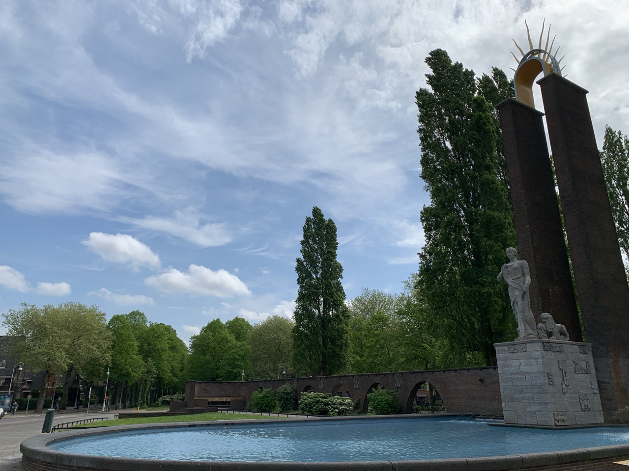
It’s the Monument Indië–Nederland on the Olympiaplein, which at the time of writing is dedicated to the “memory of the Dutch presence in the East-Indian archipelago.” My partner has taken an interest in the public monuments of Amsterdam (who petitioned for them, what do they commemorate, how did this change over the years?) so we stopped to read the plaques and take a few pictures. I, however, couldn’t help but notice something in the walls abutting the central statues of the monument:
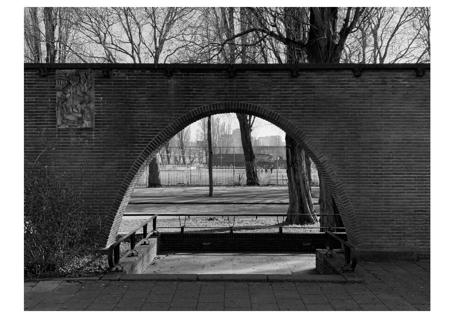
– “What is this type of arch called? It looks like a perfect catenary. Are they at all common in buildings?” I asked.
– “I don’t know, there are many different types of arches. I have an architectural dictionary at home so you can look it up. I think you just rode your bike through some glass shards, by the way; why is there always so much glass on the street in Amsterdam?”
Obviously, as the architectural dictionary told me, there is such a thing as a catenary arch [1] (the Gateway Arch in St. Louis perhaps being the most famous example), but it has a special significance when it comes to designing arches that need to support something. Before we get into that, I would be remiss if I didn’t commit two paragraphs to the bizarre history of the monument Indië–Nederland.
Originally the monument was dedicated to Jo van Heutsz, a former governor of the Dutch East Indies who is best remembered for his contribution to the “pacification” of Aceh (a region on Sumatra) during which tens of thousands of Acehnese were killed. After he croaked it himself in 1924, his supporters put money in the kitty for a mausoleum, which was built in de Nieuwe Ooster (a cemetery in Amsterdam which is also home to a funeral museum). Van Heutsz’s fans had some change left, and so they proposed erecting a monument in his memory, which now occupies roughly 300 m$^2$ in Amsterdam Zuid. I don’t know whether this was foresight on the part of the architect, but the original monument did not contain a statue resembling Van Heutsz, instead his likeness was included as a bronze plaque.
The changing attitude towards colonialism during the century that followed did not leave the monument unscathed. After the Second World War, the monument was a constant target of protests. In the 80s, the bronze plaque was stolen, and at some point someone tried blowing up one of the lions next to the central figure. In 1998, Roel van Duijn, an Amsterdam activist known for the hijinks he pulled as leader of the Kabouterbeweging (which I can only translate as the ‘Gnome Movement’) installed a blank plaque where Van Heutsz’s face had been. In 2004, finally, the monument was rebranded, and now it commemorates the relationship between the Netherlands and the Dutch East Indies1, which is an improvement, although it sounds awfully neutral given the history.
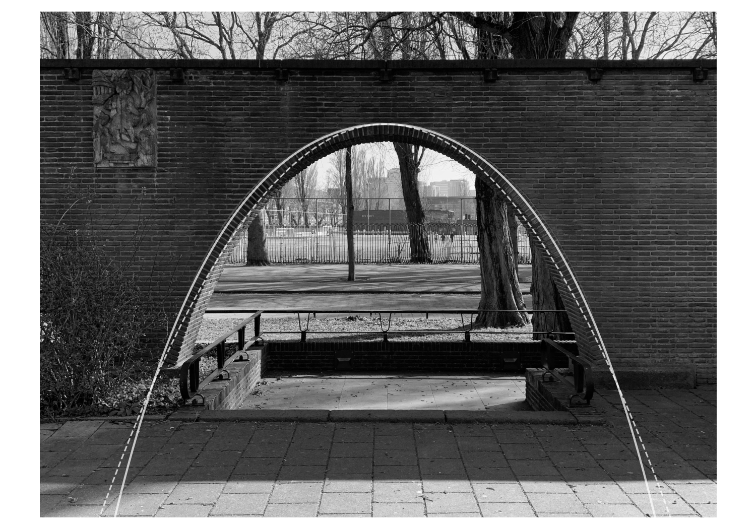
Back to the arches. Indeed, by overlapping them with a scaled $\cosh$ it’s quite easy to show that they resemble catenaries (solid line in the figure below; the dashed line is a parabola for reference). How is this related to the stability of arches, though?
Rule of middle third
Engineering textbooks have a way of lumping steps together in a way that is apparently completely obvious to mechanical engineers, but which, for physicists, can make these books a place of fear and confusion. In The Masonry Arch, for instance, Jacques Heyman casually remarks that a stack of slabs measuring $L \times L$ will ‘attempt’ to separate if a load is applied further than $L/6$ away from the center. He backs this up with a diagram that looks plausible, but which you’d have a hard time constructing yourself from physical principles. Since an arch is, in a way, a stack of slabs, it’s important to get this right, so do let’s.
When analyzing a beam that carries a load, it’s common to slice it up into thin sections that are each subject to bending (see my post on string anharmonicity for an example). The slab we’ll look at here will be one of those thin sections. Assume that the stone slab carries a load $\vec{F}_l$ applied along $-\hat{e}_y$ at a position $d\hat{e}_x$ (see figure below). This is equivalent to having a force $\vec{F}_e$ with the same magnitude applied at the center, accompanied by an effective torque $\hat{\tau}_e = -d F_l \hat{e}_z$ [3]. Assuming a stiff slab, $\vec{F}_e$ gets distributed evenly, and the stress on the supporting surface is $\vec{\sigma}_F = -F_l/L^2$. What is the effect of the torque, though?

By applying Hooke’s law to elastic materials, it can be shown [2] that the stress due to this torque is
\[\vec{\sigma}_\tau = -\frac{(x - x_0)\tau_e}{I} \vec{e}_y,\]where $I = \int x^2 dA = L^4/12$ is the bending moment, and where $x_0$ denotes the ‘plane of bending’ – which can here be found to coincide with $x = 0$ by requiring $\int\vec{\sigma}_\tau \cdot d\vec{A} = 0$. The right-hand side of the slab will always experience a compressive stress (since both $\vec{\sigma}_F$ and \(\vec{\sigma}_\tau\) are pointing down), but on the left-hand side they work in opposite directions. The stress at $x = -L/2$ is given by
\[-\frac{F_l}{L^2} + \frac{F_l d}{L^3},\]which changes sign around $d = L/6$, meaning the stress goes from compressive to tensile (things get pulled apart) if $d$ becomes too large [3]. The problem with masonry arches is that a lot of the materials used (the stones, the mortar keeping them together) are not able to transmit tensile stresses well, in much the same way as a chain cannot transmit compressive stresses, meaning that the assumptions we’ve made on these materials being elastic stop being valid. Arches under (too much) tension collapse, just as chains under compression buckle. The interpretation of this result, then, is that whatever loading is applied to a slab better be restricted to the middle third ($|d| \leq L/6$) of its normal surface area.
In our current day and age this is less of a problem, owing to the invention of reinforced concrete. We do well to remember, though, that concrete (like masonry) has poor tensile properties, which is the entire point of reinforcing it with steel bars.
Line of thrust
When is an arch at risk of collapse? In 1748, this became a particularly pertinent question to Pope Benedict XIV, who found himself in a dilly of a pickle when the dome of St. Peter’s Basilica formed cracks. With bits falling on the floor every day, he enlisted Giovanni Poleni, a physicist, to analyze the risk, and to come up with recommendations for reinforcing the structure [4]. The dome had separated into wedges which Poleni analyzed in opposing pairs. Poleni knew that arches and chains were two sides of the same coin, and that you could get a sense of the way stresses were distributed in an arch by turning the problem on its head and weighting a chain with the same (relative) distribution of loads as is applied to the arch [5]. Using his ‘catenary in the coal mine,’ Poleni found that the line he obtained like this lay within the structure of the dome, and concluded it was safe. He did recommend reinforcing the base so that it could withstand the horizontal thrust, which was subsequently done. The dome of St. Peter’s stands to this day.
In current parlance we’d say that Poleni performed an analog simulation of the stability of St. Peter’s dome. His method, using a scale model to calculate the ‘line of thrust,’ went a very long way: Antoni Gaudi also used it to design some of the many arches and domes in his buildings [1]. Since arches, domes, and other static structures typically have more unknowns than equilibrium equations, they are indeterminate, meaning we cannot calculate all the internal forces without additional information. This isn’t as much of a problem as you might think. You can, for instance, use this type of approach to demonstrate that an arch has a stable equilibrium, which is where the line of thrust comes in.
The line of thrust indicates the directions and points along which the internal force is transmitted through a structure. If the arch is cut along a given plane, one can think of the thrust line as indicating the point and direction in which a force should be applied to maintain equilibrium. Owing to the indeterminacy it isn’t unique, but if you can find a thrust line that lies sufficiently deep within the arch, it means that it’s stable.
Part of the indeterminacy is caused by the arch abutment typically not consisting of a single point, meaning the line of thrust can cross it in several places; it’s also generally unclear how the reaction forces are distributed between the abutments. Compare this to a hanging chain which is highly symmetric and has point-like connections to the structure it’s mounted to. Changing the loading of an arch will change the shape of the line of thrust. While a chain can adjust itself to a change in loads, an arch does not have this option, and will become unstable if the line deviates too far from the center line. Exactly when this happens depends on material properties. While the mortar that holds the arch elements (‘voussoirs’) together has poor tensile strength, it does have some, so an arch doesn’t immediately collapse if tensile stresses develop. In practice, safety margins are taken, making these details less relevant.
Back to the catenary, because is a freely hanging chain indeed exactly the same as an arch? The catenary that you derive in undergrad supposes that a chain carries no load except for its own weight. Surely the optimal shape should change if you use the typical weighting of an arch? Indeed, if you’re on the market for an infinitely thin arch that can support nothing but itself, look no further than the catenary; if not, however, you need to do a little calculation.
Never break the chain
I meant to do something interesting here and derive the thrust line of a loaded arch using the principle of least action. The principle of least action was about as yielding as a beam of prestressed concrete, though, so now this will be left as an exercise to the reader. Instead, here’s a simple statics derivation for the interested reader. The uninterested reader should feel free to jump to the boxed result below.
We assume the arch has uniform height $h$ and that the center line is given by $y(x)$, which is symmetric around $x = 0$ where its maximized. The load of the rest of the wall on a horizontal element $dx$ is then $\mu(h-y(x)) dx$, where $\mu$ is the weight of the wall per unit area. We’d like to find $y(x)$ so that it follows the thrust line.

Using the construction from the figure above, and by requiring that the total horizontal force equals zero, we find that
\[(P+dP) \cos(\alpha + d\alpha) - P\cos(\alpha) \approx dP \cos(\alpha) - P d\alpha \sin(\alpha) = 0,\]which, after division by $dx$, we can restate as
\[\frac{d}{dx} P \cos(\alpha) = 0.\]Since $P\cos(\alpha)$ is constant throughout the arch, it must be equal to the horizontal thrust $|\vec{H}|$ that’s acting on it at either side. From a similar condition on the vertical forces we find:
\[\frac{(P+dP)\sin(\alpha + d\alpha) - P\sin(\alpha)}{dx} = \mu(h-y),\]which is equivalent to
\[\frac{d}{dx} P\sin(\alpha) = \mu(h-y).\]Sheer insight, not at all related to prior knowledge of the solution, suggests we now investigate the derivative of $\tan(\alpha)$. It will be useful to observe that $\tan(\alpha) = -dy/dx$, where we pick up the sign because of how the differentials $dy$ and $dx$ are defined in the figure above. So:
\[\begin{align} \frac{d}{dx} \tan(\alpha) = - \frac{d^2y}{dx^2} &= \frac{d}{dx} \frac{P \sin(\alpha)}{P \cos(\alpha)} \\ \Rightarrow \frac{d^2y}{dx^2} &= \frac{\mu}{H} (y - h), \end{align}\]where we used $\tan\alpha = \frac{\sin\alpha}{\cos\alpha}$, and the fact that $P \cos(\alpha) = H$ (which is constant). As a trial solution, we can use $y(x) = A e^{\beta x} + B e^{-\beta x} + h$. Since this should be symmetric around $x = 0$, we can set $B = A$; from substitution in the differential equation we obtain $\beta^2 = \mu/H$. Using the definition of the hyperbolic cosine this becomes:
\[y(x) = 2A \cosh(\beta x) + h.\]We impose several boundary conditions. One is that we’d like the line of thrust to pass through the crown of the arch, i.e. $y(0) = h - a$, the other is that we want it to go through $y=0$ at $x = \pm L/2$. From the former condition we find $2A = -a$, and from the second one we obtain:
\[\beta = \frac{2}{L} \operatorname{arcosh}\left(\frac{h}{a}\right).\]Putting everything together, we find:
\[\boxed{ y(x) = -a\cosh\left[ \frac{2x}{L} \operatorname{arcosh} \left( \frac{h}{a}\right) \right] + h. }\]The standard catenary is simpler: $a \cosh(x/a)$, the difference is that the loading of an element of the arch we’re considering depends on its distance to the floor.
How close is the line of thrust to the arch in the case of the monument? While I don’t have the exact measurements, we can make some estimates: A standard brick is about $50~\mathrm{mm}$ thick, and allowing for an additional $10~\mathrm{mm}$ for mortar, I estimate $h = 2.8~\mathrm{m}$ and $a = 0.7~\mathrm{m}$. A standard Dutch pavement tile, furthermore, is $30~\mathrm{cm}$ wide, which brings me to $L = 4.2~\mathrm{m}$. Plotting $y(x)$ using these estimates (and after some justifiable scaling), we see that the arch indeed roughly follows the line of thrust:
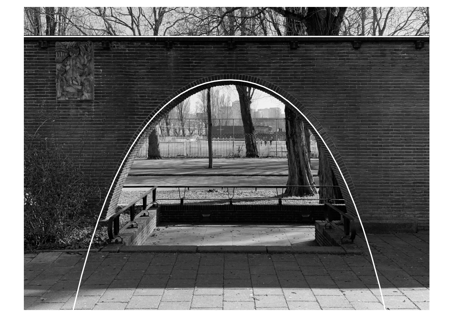
It should be obvious that the arch does not follow the standard catenary, but rather a weighted (or scaled) one. This isn’t at all surprising, since the loading isn’t homogeneous. As far as chains go, you’d get something resembling this thrust line by weighting a chain more heavily on its sides than in its center, stretching it and effectively making it wider.
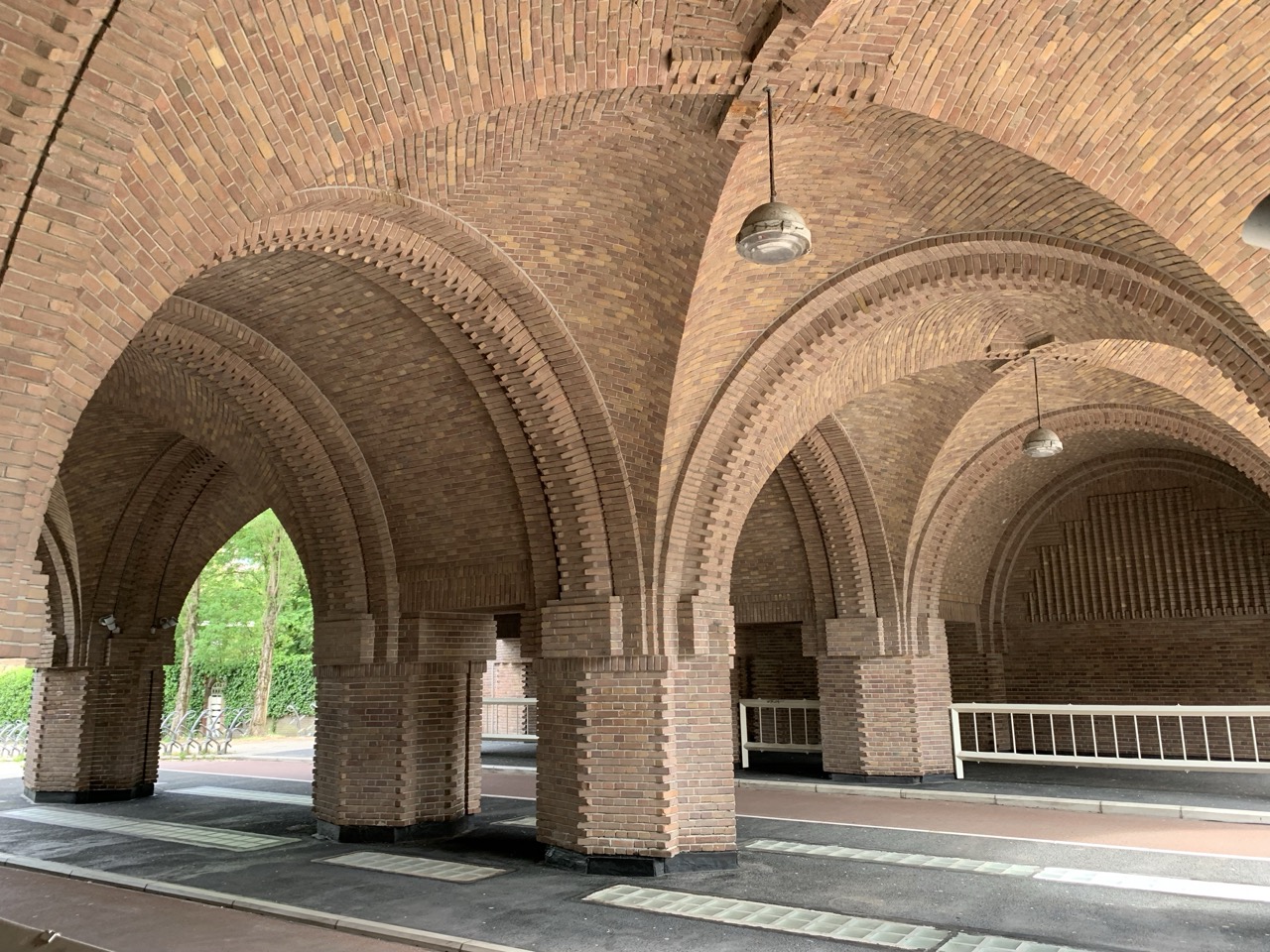
Amsterdam (and in particular the southern part) is home to many great examples of architecture like the Monument Indië–Nederland. The architects of the Amsterdamse School, in particular, used brick in beautiful and imaginative ways (so it’s perhaps not surprising that this style is part of a larger international movement known as ‘brick expressionism’). Whenever I’m in the area, I find myself marveling at how these architects used brick both decoratively and structurally. Across from the monument, you can find another exponent: the Amsterdams Lyceum, which is still in use as a school. If you ever find yourself biking in the neighborhood, I can heartily recommend taking the bike path that runs underneath it, although you might want to get off for a minute to admire the arches and vaults that support the building.
References
[1] E.J. Haslinghuis and H. Janse, Bouwkundige Termen, Fifth Edition, Primavera Pers (2005).
[2] J.M. Gere and B.J. Goodno, Mechanics of Materials, Seventh Edition, Cengage Learning (2009).
[3] F.-H. Cheng, Statics and Strength of Materials, Second International Edition, McGraw–Hill (1998). Available online.
[4] J.J. O’Connor and E.F. Robertson, “Giovanni Poleni,” in: MacTutor History of Mathematics, St. Andrews (2000). Available online.
[5] Jacques Heyman, The Masonry Arch, Ellis Horwood Limited (1982).
Footnotes
-
The ‘Indië’ in the official name of the monument refers to the Dutch East Indies which ceased to exist in 1949 when Indonesia officially became independent. Exactly what the monument is supposed to commemorate is an uncomfortable question, which is probably why it ended up with such a generic name. ↩